Design/Build Fuel Skid System

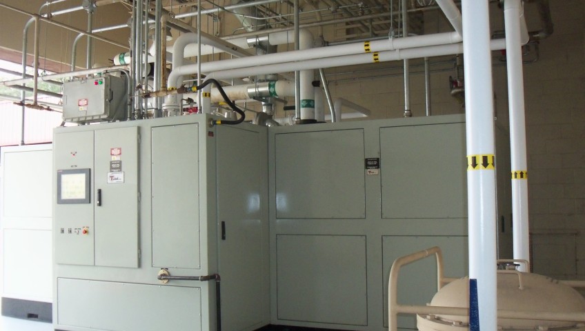
Cape Design Engineering was responsible for a turnkey design, fabrication and installation of a new semi-automated, high pressure fuel skid system (FSS) and installation of new stainless steel supply distribution piping in the south section of building 795, Fleet Readiness Center Southeast (FRCSE) Jacksonville, Florida. The FSS is capable of delivering 400 gallons of calibration fluid (MIL-C-7024 Type II) per minute (GPM) at a line pressure of 1650 PSIG to eight test stands operating at full capacity with no interruptions. The new stainless steel supply distribution piping with test stand connection points were installed prior to the installation of the pump systems to negate operational down time. The FSS incorporated state-of-the-art electronic PLC controls that are easily supportable for the next 15 years and provide intuitive capacity management and control. CDE performed non-destructive X-Ray testing of all pipe welds. CDE provided complete training of system operations. A fuel/water separator was incorporated in the open loop return line to ensure water free calibration fluid. The calibration fluid has a flash point of 104°F, therefore, the pump skid was rated as a Class 1 Division 2 hazardous environment. All electrical components complied with the appropriate NEC requirements for a Class 1 Division 2 environment. Complete chilled water cooling system (47 °F water), 100 PSIG shop air pneumatic system, and 408 volt electrical distribution from MCC to power these systems were designed by CDE.

The benfits of the design include a highly reliable, fully automated, least maintenance cost fuel skid with the following features: Appropriate vibration dampening was employed to reduce stress on hardware. Commercial-Off-the-Shelf components were used in all instances. Pump, filter, valve placement, and orientation were geared toward ease of maintenance support and accessibility. Ensuring successful purge cycles during each start up was a challenge. CDE developed a sequence of operations, tested each one, and commissioned the systems to ensure that the purge cycle is successful without any damage to the system each time. A rupture disc rated to burst at 2000 PSI and a pressure relief valve were installed in each branch supply pipe and vented back to the open loop return pipe for additional safety. The FSS control system was configured to operate as a stand-alone system with fully redundant manual controls. The PLC manages the use of the available pumps to satisfy the instantaneous flow demand of the connected test stands.

Renovate Airfield Rinse Rack

CDE was tasked with the design/build to repair the existing aircraft wash and rinse racks. The wash system that was originally installed did not work properly. The new design incorporates a system that removes the surfacants from the wash water and reuses the water instead of the current system that is supposed to do this but doesn’t function properly so all of the water is currently being processed by the water treatment plant and new potable water is used to wash each plane. The new system will recycle the water and the only new water necessary to be added to the system is water that evaporates or is not captured for processing.

The rinse rack which is adjacent to the runway and rinses each aircraft that passes through the taxiway throat. The current system does not recycle any water and has to use fresh water for each plane, a total of 1,000 gallons per plane with 95 planes being rinsed weekly. This portion of the project entails the demolition of the existing electrical feed and transformer, the pump vault, and storage tank with the replacement with a new transformer in an underground cast-in-place concrete vault (nothing at the site can protrude more than 2” above grade), a new 30’ by 13’ by 10’ deep pump vault, new pumps and water processing equipment for installation inside the vault, new 10,000 gallon oil/water separator, new 5,000 gallon water storage tank, extended trenches and spray bar piping to accommodate larger aircraft, and relining the existing storm water piping that will be connected to the water processing system.

This project had many challenges. The vault that houses all the pump, piping, and electrical had to be constructed underground with no protrusions over 2.5 inches above the runway. CDE designed a complete water proof vault for all pumping systems and a separate containment for the main transformer. All the drains were collected to a sump and dual pumps were installed to ensure that no flooding would occur in the vault. Complete telemetry has been installed to provide warnings and safety control valve isolation in case of hurricane or heavy rain events.

CDE provided complete civil site design that included utilities (water, sewer, storm sewer, communications, and electrical), grading and paving. Pavement included taxiway rigid pavement. Electrical design included transformer design, lighting, and primary and secondary distribution.

Restoration and Renovation to the NASA Locomotive Shelter

he NASA Railroad System was put into use in 1963 once the Florida East Coast Railway added a 7.5 mile connection from its mainline across the Indian River Lagoon. Its primary use at that time was for the transport of heavy building materials for the construction of facilities such as the Vehicle Assembly Building (VAB) in support of the newly chartered Apollo Program, a program that would eventually change the face of all space travel and human history.

The use of the rail system didn’t end at transporting building materials. The rail system became an integral part of moving various space flight vehicles and equipment to different launch sites at Cape Canaveral Air Force Station and NASA. Once the Apollo program was phased out and the Space Shuttle Program was chartered, the NASA Rail System took on another role; it became the delivery and transport system of the Solid Rocket Boosters used to get the Space Shuttle into orbit. The boosters were assembled by Thiokol across the country in Utah and shipped via rail in sections. After a seven day journey the sections of the boosters would arrive at the Jay Jay rail yard exchange in North Titusville. From there the NASA Locomotive team transported the sections over the Indian River across the Jay Jay Bridge to their assembly point.

Needless to say, parts of the rail system have become aged and worn in their 40 plus years of service. One of those facilities is the Locomotive Shelter located just down the street from the VAB. The Locomotive shelter is just one of many invaluable parts of the NASA Rail System. In 2009, it was determined that the locomotive shelter needed a make over. NASA contracted with CDE to come up with a design to refurbish and restore the aging facility.

CDE’s solution entailed designing and replacing the pre-engineering metal building skin (roof and siding) with aluminum panels to meet current wind loads, replacing all purlins and girts with new corrosion resistant sections, perform corrosion control on the pre-engineering metal building frame, and construct a brand new office building for the locomotive shop staff.  The new facility features office spaces, break rooms, locker rooms, toilets with shower, and a mechanical room.  In addition to that, CDE provided site design that included site surveying, grading, storm water, new utilities (water, fire water, sewer, communion and power) to the new and existing facility.  CDE also designed and constructed a new on-site storage building.