NASA Kennedy Space Center Headquarters Building Threshold Inspection Services

In efforts to reorganize and redirect itself for the next wave of space travel NASA developed a new master plan for Kennedy Space Center. This plan includes the design and construction of a new seven-story, 200,000-square foot Headquarters Building and the subsequent retirement and demolition of the existing HQ building. On October 7, 2014 ground was broken and the project was set into motion.

What is CDE’s role in this project? While CDE did not design the new Headquarters Building, nor are we involved in its construction, we are serving as the Threshold Inspection Agent during its construction.

When a building in Florida meets a certain criteria, based on height and occupancy, it is a requirement by the Florida Building Code that a special inspector routinely inspect the structural elements of the building throughout its construction phases.  CDE is proudly supporting NASA in this role and is honored to have a part in construction of this historic new facility.

Design/Build NASA Generator RICE-NESHAP Compliance Projects

Cape Design Engineering provided full Design/Build services for a time critical project to bring three power generation sites into compliance with RICE-NESHAP regulations (five generators at the C-5 substation, two generators at the CD & SC Facility, and two generators at the Press Site launch observation site). These generators are critical since they serve the the Vehicle Assembly Building and surrounding areas of NASA. CDE processed a Construction Air Permit from the Florida Department of Environmental Protection (FDEP) for making modifications to the 9 generators currently covered under an active air permit. This effort was coordinated with the KSC Environmental Assurance Branch (EAB). The permit was obtained from FDEP ahead of the schedule due in part to the thorough, clear and concise permit application.

CDE’s design service included structural, electrical and controls engineering for all three sites. Structural provided design to support the new silencer/catalysts. This effort included some finite element modeling of existing steel support towers and their modifications to support the new silencer/catalysts. Electrical design included power, Lightning protection, primary power distribution and controls. The controls tied new catalyst metering and monitoring devices into the existing power distribution.

After completing the mechanical modifications on the generators, CDE conducted comprehensive testing to ensure all generators complied with the EPA Reference Test Method requirements. This testing was coordinated with the state of Florida and local environmental jurisdictions as required by RICE-NESHAP, FDEP rules, and the Title V operating permit. The Compliance testing verified acceptable CO reduction was achieved.

CDE’s design and construction effort met the RICE-NESHAP requirements of reducing CO concentration by 70% when comparing measurements before and after the oxidation catalyst. CDE’s design and scheduling ensured that each site maintained the ability to provide standby power for their part of the NASA KSC power distribution system safely.

Design/Build Fuel Skid System

Cape Design Engineering was responsible for a turnkey design, fabrication and installation of a new semi-automated, high pressure fuel skid system (FSS) and installation of new stainless steel supply distribution piping in the south section of building 795, Fleet Readiness Center Southeast (FRCSE) Jacksonville, Florida. The FSS is capable of delivering 400 gallons of calibration fluid (MIL-C-7024 Type II) per minute (GPM) at a line pressure of 1650 PSIG to eight test stands operating at full capacity with no interruptions. The new stainless steel supply distribution piping with test stand connection points were installed prior to the installation of the pump systems to negate operational down time. The FSS incorporated state-of-the-art electronic PLC controls that are easily supportable for the next 15 years and provide intuitive capacity management and control. CDE performed non-destructive X-Ray testing of all pipe welds. CDE provided complete training of system operations. A fuel/water separator was incorporated in the open loop return line to ensure water free calibration fluid. The calibration fluid has a flash point of 104°F, therefore, the pump skid was rated as a Class 1 Division 2 hazardous environment. All electrical components complied with the appropriate NEC requirements for a Class 1 Division 2 environment. Complete chilled water cooling system (47 °F water), 100 PSIG shop air pneumatic system, and 408 volt electrical distribution from MCC to power these systems were designed by CDE.

The benfits of the design include a highly reliable, fully automated, least maintenance cost fuel skid with the following features: Appropriate vibration dampening was employed to reduce stress on hardware. Commercial-Off-the-Shelf components were used in all instances. Pump, filter, valve placement, and orientation were geared toward ease of maintenance support and accessibility. Ensuring successful purge cycles during each start up was a challenge. CDE developed a sequence of operations, tested each one, and commissioned the systems to ensure that the purge cycle is successful without any damage to the system each time. A rupture disc rated to burst at 2000 PSI and a pressure relief valve were installed in each branch supply pipe and vented back to the open loop return pipe for additional safety. The FSS control system was configured to operate as a stand-alone system with fully redundant manual controls. The PLC manages the use of the available pumps to satisfy the instantaneous flow demand of the connected test stands.

NASA’s SSPF Science Annex

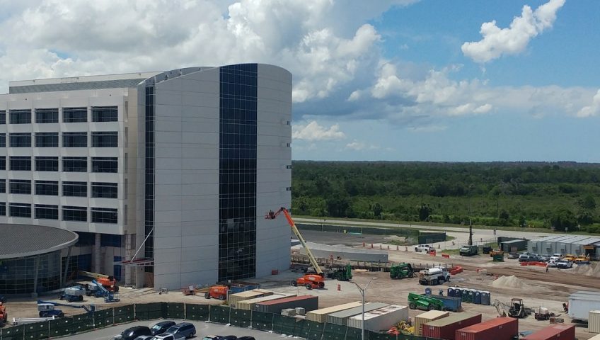
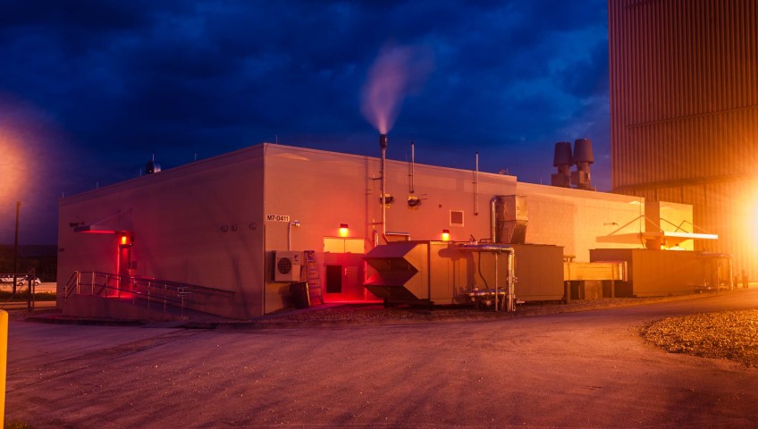
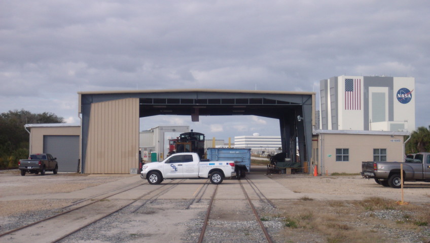
The SSPF Science Annex is a new building located adjacent to the Space Shuttle Processing Facility. It serves as a science laboratory which supports manned space missions. The SSPF Science Annex is located at Kennedy Space Center.

CDE’s design team performed, complete design including site civil, architectural, structural, electrical, mechanical, plumbing, process piping, controls, fire detection and protection as well as data system. This building is designed with 100% redundancy in system operation without single point failure. CDE’s construction team completed the construction of this facility and it was commissioned by a third party. The entire building and systems were modeled using BIM.

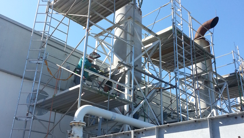
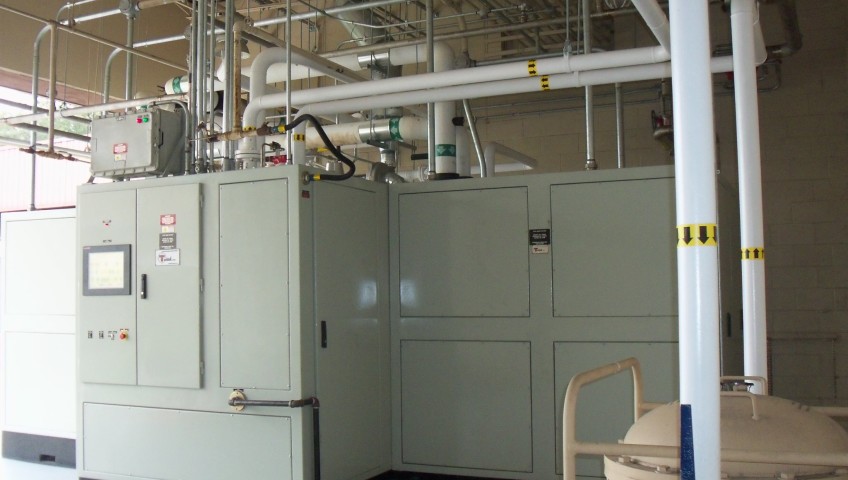
CDE’s design team also had the difficult task of maintaining precise temperature and humidity control in each of the spaces over a wider range than that of a normal building. The other, bigger challenge was to accommodate all the mechanical systems with redundancy in less than a 500-square-foot space. Because the site was so limiting, CDE had to add a mezzanine to accommodate extensive systems. CDE also had to fit two steam boilers, five humidifiers, three hot water heaters, water treatment, a deionized water generator, DI water storage tank and an exhaust fan system within this 500 ft.² space. In addition, the fire protection riser had to be installed within the same space with code required clearances. The architectural aspects of construction came with several challenges. The building had to be airtight and moisture-proofed. The surfaces were required to be resistant to repeated cleaning cycles.
Another challenge was a design that allowed pressure relationships to be maintained over a wide range of air flow rates to the individual spaces. Additionally, the commissioning of the building was a huge challenge because of several possible system/control failure scenarios. These systems were rigorously tested and validated for each of those scenarios.
This building utilizes every possible utility, such as chilled water, compressed air, DI water, high and low temperature hot water, steam, condensate, and natural gas. This project was completed on time and within budget.

There are several ECMs incorporated for energy savings for this facility compared to a standard facility and this building has been designed for LEED Silver Certification. The energy conservation features included the following: Chilled water system was provided for this 5,700 sq.ft conditioned spaces. In addition, VFD control for air handlers and exhaust fans, Occupancy sensors, Demand-controlled ventilation based on mode of operation, High-efficiency steam boilers and hot water heaters, SCR controls for every heater in the facility for precise temperature control, Supply air temperature reset control, a complete direct digital control system for monitoring, measurement and verification were provided. Since it is a lab building, there were unique requirements for precise temperature and humidity range controls for each of the spaces. Modulation of supply and exhaust with VFDs to maintain positive pressure in the building was provided. The building saves 35% more energy compared to a conventional building design.

Corry Station Track & Field Replacement

Projects entails the installation of a combination football/soccer synthetic turf field and the rehabilitation of the surrounding running track. The track portion involves an asphalt mil & overlay before installing a new track surface. Additional scope includes civil and site work to establish a drainage system for the field before installing the synthetic turf field.

Kings Bay Athletic Track & Field

This design-build project consisted of replacement of existing soccer/football field grass turf located inside base track with new synthetic surface. The existing grass surface does not have ample recovery between events held at the complex. Installing synthetic turf will provide a reduced maintenance facility that can handle the multitude of events held at the facility while providing an aesthetically pleasing appearance. The following are highlights of the project:

  • Replace grass area inside of track with synthetic surface. Surface area converted to synthetic turf is approximately 102,000 square feet. The area covered the existing soccer/football field grassy area inside the track area.
  • Installed a complete, premium quality synthetic turf consisting of a vertical draining gravel blanket and nominal 2.25” long polyethylene paralleling slit and dual mono-filament blended fibers, tufted into a primary backing with a secondary backing consisting of a minimum of 22 ounces of urethane per square yard with a resilient fill surface system consisting of silica sand and crumb rubber granules.
  • The turf shall have the system’s shock attenuation shall have an average G max value of 100-125.
  • The existing eight lane track surface to be resurfaced, pained and stripped.
  • Removed and disposed of existing scoreboard, soccer goals and electrical pedestal.
  • Provide site/civil design that included storm water calculations and management along with permitting from regulatory state agency.

This design-build project was completed over one month ahead of schedule.

Renovation of Building 614

CDE was tasked with the complete interior renovation of Building 614 (the NAS Jacksonville gymnasium) with all new wall, floor, and ceiling finishes, new lighting, new HVAC equipment, and refinishing two racquetball court floors and a basketball court floor. The building was originally built in 1945 and is a two-story, 12,000 square foot facility with workout room, locker rooms, saunas, office space, and a massage therapy room. The current HVAC system uses chiller water as the cooling medium but the system is not balanced and cannot meet the demand. Many of the ceiling tiles were sagging because of the high humidity in the facility.

The new HVAC design incorporates a heat recovery variable flow mini-split refrigerant based system with minimal ductwork. Soffits were designed to hide the refrigerant and condensate piping as several of the rooms do not have drop or gypsum ceilings. All of the showers and restrooms have been redesigned to remove and replace all partitions and fixtures. The steam rooms have been damaged due to the use of coarse and abrasive cleaning techniques on the tile and have moisture behind the tile. The new design repairs the damaged walls and replaces all the ceramic tile on the walls, floors and ceiling of the steam rooms.

In addition to the HVAC effort of the project, some of the additions and enhancements to the gym are a new open but covered outside training facility, refinished sauna/stream rooms, new equipment such as flat screen TVs, refinished gym floor with striping and new floor finishes.

Energy conservation was a critical part of this project. Some of the conservation measures incorporated with design includes:

  • Low e- windows throughout the building.
  • Separate VRF system for the first floor (exercise room area) and the second floor (locker rooms). These units are zoned ductless systems that meet the designated areas specific demands.
  • Zoned ductless variable flow refrigerant system (18 fan coil units with two condensers).
  • All exercise room units are ceiling suspended with target cooling sensors.
  • Occupancy sensors for lighting control throughout the facility.
  • OA control based on occupancy profile and to maintain building pressure during all occupied hours.
  • T-8 lights installed throughout the facility to improve lighting and lighting efficiency.
  • New controls allow for variable set points on supply air temperature for the outside air conditioning unit during summer and winter months to maximize energy savings.
  • A well ventilated and tempered laundry facility with its envelope isolated from the rest of the facility.
  • The new condensers have variable speed compressors with (18.1 IEER for first floor unit and 20.8 IEER for the second floor unit).
  • Individual room temperature control for the offices/lobby for improved comfort and energy savings.

Renovate Airfield Rinse Rack

CDE was tasked with the design/build to repair the existing aircraft wash and rinse racks. The wash system that was originally installed did not work properly. The new design incorporates a system that removes the surfacants from the wash water and reuses the water instead of the current system that is supposed to do this but doesn’t function properly so all of the water is currently being processed by the water treatment plant and new potable water is used to wash each plane. The new system will recycle the water and the only new water necessary to be added to the system is water that evaporates or is not captured for processing.

The rinse rack which is adjacent to the runway and rinses each aircraft that passes through the taxiway throat. The current system does not recycle any water and has to use fresh water for each plane, a total of 1,000 gallons per plane with 95 planes being rinsed weekly. This portion of the project entails the demolition of the existing electrical feed and transformer, the pump vault, and storage tank with the replacement with a new transformer in an underground cast-in-place concrete vault (nothing at the site can protrude more than 2” above grade), a new 30’ by 13’ by 10’ deep pump vault, new pumps and water processing equipment for installation inside the vault, new 10,000 gallon oil/water separator, new 5,000 gallon water storage tank, extended trenches and spray bar piping to accommodate larger aircraft, and relining the existing storm water piping that will be connected to the water processing system.

This project had many challenges. The vault that houses all the pump, piping, and electrical had to be constructed underground with no protrusions over 2.5 inches above the runway. CDE designed a complete water proof vault for all pumping systems and a separate containment for the main transformer. All the drains were collected to a sump and dual pumps were installed to ensure that no flooding would occur in the vault. Complete telemetry has been installed to provide warnings and safety control valve isolation in case of hurricane or heavy rain events.

CDE provided complete civil site design that included utilities (water, sewer, storm sewer, communications, and electrical), grading and paving. Pavement included taxiway rigid pavement. Electrical design included transformer design, lighting, and primary and secondary distribution.

Restoration and Renovation to the NASA Locomotive Shelter

he NASA Railroad System was put into use in 1963 once the Florida East Coast Railway added a 7.5 mile connection from its mainline across the Indian River Lagoon. Its primary use at that time was for the transport of heavy building materials for the construction of facilities such as the Vehicle Assembly Building (VAB) in support of the newly chartered Apollo Program, a program that would eventually change the face of all space travel and human history.

The use of the rail system didn’t end at transporting building materials. The rail system became an integral part of moving various space flight vehicles and equipment to different launch sites at Cape Canaveral Air Force Station and NASA. Once the Apollo program was phased out and the Space Shuttle Program was chartered, the NASA Rail System took on another role; it became the delivery and transport system of the Solid Rocket Boosters used to get the Space Shuttle into orbit. The boosters were assembled by Thiokol across the country in Utah and shipped via rail in sections. After a seven day journey the sections of the boosters would arrive at the Jay Jay rail yard exchange in North Titusville. From there the NASA Locomotive team transported the sections over the Indian River across the Jay Jay Bridge to their assembly point.

Needless to say, parts of the rail system have become aged and worn in their 40 plus years of service. One of those facilities is the Locomotive Shelter located just down the street from the VAB. The Locomotive shelter is just one of many invaluable parts of the NASA Rail System. In 2009, it was determined that the locomotive shelter needed a make over. NASA contracted with CDE to come up with a design to refurbish and restore the aging facility.

CDE’s solution entailed designing and replacing the pre-engineering metal building skin (roof and siding) with aluminum panels to meet current wind loads, replacing all purlins and girts with new corrosion resistant sections, perform corrosion control on the pre-engineering metal building frame, and construct a brand new office building for the locomotive shop staff.  The new facility features office spaces, break rooms, locker rooms, toilets with shower, and a mechanical room.  In addition to that, CDE provided site design that included site surveying, grading, storm water, new utilities (water, fire water, sewer, communion and power) to the new and existing facility.  CDE also designed and constructed a new on-site storage building.

NASA kA Band Antenna Array

The effort for this design/build project entailed providing three new concrete mat support foundations in a 60 m equilateral triangle formation to support three new 12 m dish antennas with pedestals; providing a concrete pad at the center of the equilateral triangle for mounting antenna monitoring equipment; providing foundation and erecting of the command center; and installing utilities such as potable water, sanitary sewer, electrical power, communications, fiber optics, fire alarm, lightning protection, and grounding systems for the antennas and the command center support area. CDE also provided HVAC to each of the antennas.

CDE provided full design services for this project such as civil, structural, and electrical.  The civil effort involved preparing the existing project site and existing utility lines (water and sewage) for use within the command center.  A new backflow preventer with shut off valves and valve box was provided for the new waterline that connects the existing waterline to the command center.  The reinforced concrete mat footings for the dish antennas were supported on augercast concrete pile foundations and were designed to support all applicable dead and wind loads in accordance with the Florida Building Code.

The equipment for electrical power distribution for the antennas was installed outdoors on freestanding racks and counterpoise rings were installed around the antennas and command center to serve as the above grounding system.  The lightning protection systems for the antennas and command center were connected to the above grounding system.  The fire alarm system for the antennas included smoke detectors at each antenna pedestal and the fire alarm system for the command center included smoke detectors and notification devices connected to the fire alarm panel within the command center.  The communication system is fiber optic.